|
Society of Automotive Engineers
1998 Conference and Exhibition February, Detroit The Steel Unibody:
|
|
ABSTRACT
Despite repeated challenges from alternative materials and processes, the stamped and spot welded steel unibody remains the near-unanimous choice of automakers for vehicle body-in-white (BIW) structures and exterior panels in volume production. Conventional steel's only weakness is mass; aluminum and polymer composites offer the potential for considerable mass savings, but generally at a higher cost. Efforts within the automakers as well as by outside organizations such as the international steel industry’s Ultra Light Steel Auto Body (ULSAB) program are underway to improve the steel unibody's mass and cost position. To reduce cost, it is first necessary to identify cost. The measurement of cost for a complex system such as an automobile BIW is far from a trivial task. This paper presents an analytical approach to understanding the manufacturing cost for a conventional steel unibody. The results of this cost analysis are then used to outline a strategy for future cost reduction. |
|
INTRODUCTION
The case study steel unibody is a body-in-white that might be manufactured in North America in the 2000 timeframe. To avoid the difficulties of using an existing vehicle from a specific manufacturer, the FRV is a hypothetical “construct” intended to represent an “averaging” of a midsize, four-door sedans such as the Chevrolet Lumina, the Chrysler Concorde, the Ford Taurus, and so on. The downside to opting for this generic approach is the lack of a well-defined vehicle design and manufacturing processes. To provide a non-proprietary platform for cost analysis not just by automakers, but also by materials and component suppliers and other non-automaking parties, this approach is necessary. Compensating for the resulting lack of information is the subject of the Methodology section below. The remainder of this paper continues as follows.
|
|
STEEL UNIBODY OVERVIEW
The steel unibody includes structural stampings with the exception of bumper beams and engine and suspension subframes. A complete set of Class-A exterior panels is also included: hood, roof, decklid, fenders, front and rear doors, and quarter panels. The overall body-in-white mass is 250 kg. Eighty percent of this mass is conventional mild steel, with the remaining 20% high strength steel. This material makeup is representative of the bulk of vehicles manufactured today, although some new vehicles are starting to incorporate higher levels of the high strength material. The total piece count for the steel unibody is 237, an aggressive figure chosen to represent a best-case Year 2000 BIW implementation. The majority of vehicles in production today are estimated to have piece counts in the 220-250 range. A breakdown of the piece count by stamping type is shown below.
The steel unibody is stamped and spot welded from sheet steel. |
|
Fabrication
Stampings are a fabricated on a range of press types that include tandem press lines, transfer presses, and progressive die presses. Of the three, tandem and transfer presses take cut blanks as inputs, whereas progressive die presses are fed directly from a coil of sheet steel. The tandem press lines are used for the largest parts as well as for many medium parts. Many of these parts are stamped double-attached as explained above. Transfer presses are used for simpler medium parts that do not require the deep drawing capabilities of double action tandem presses. Progressive die stamping is used for smaller parts that are always single-attached parts. A breakdown of the various stamping runs is presented below.
All of the stamping presses for the steel unibody are non-dedicated. The non-dedicated scenario means that unused press capacity is assumed to be used for parts on another vehicle, and that the cost of this excess press capacity is not billed to this particular vehicle. |
|
Assembly
The steel unibody assembly plant is sized for a production rate of 60 vehicles per hour after downtime is factored in. Four general types of assembly stations are considered: manual and automated sub-assembly and manual and automated final assembly. The total number of spot welds is broken down by the type of station that performs the welds as shown above. The weld placement speed and number of weld heads per station then determines the number of stations of each type. The distinction between sub-assembly and final assembly is that sub-assembly requires a dedicated tool or fixture. With final assembly, on the other hand, it is assumed that the body-in-white itself serves as the “fixture” on which additional welds are made. Manual operations assume the presence of laborers moving parts to and from the welding area, as opposed to automated assembly that requires only on the order of one laborer for every five to ten stations. Assembly is assumed to be dedicated. The implication of this choice is that the entire investment in the assembly facility is allocated to the steel unibody regardless of how many vehicles are actually produced. The Methodology section that follows introduces the approach used to take the vague and generic description above in order to generate a detailed cost analysis. |
|
METHODOLOGY
To understand manufacturing cost, IBIS employs an approach called Technical Cost Modeling. The technique [1],[2] is an extension of conventional process modeling, with particular emphasis on capturing the cost implications of material and process variables and changing economic scenarios. Technical Cost Models (TCM) consist of two elements: a framework of algorithms or equations, and the data that fills this framework. A cost modeling exercise is characterized by the following steps.
The goal of Technical Cost Modeling is to understand the costs of a product and how these costs are likely to change with changes to the product and process. Specifically, this includes the breaking down and ranking of cost into its constituent elements as listed below.
Once these costs are established, sensitivity analysis can be performed to understand the impact of changes to key parameters.
IBIS has applied this methodology repeatedly for a broad range of automotive applications.
The remainder of this Methodology section describes how Technical Cost Modeling is applied to analyze cost for the generic steel unibody under consideration. The definition of the steel unibody as introduced on the preceding pages is the result of several decisions and steps as outlined below. The first decision is that a generic reference case is needed. The primary obstacle in using such a design is that it first needs to be created to a level of detail sufficient as an input to cost modeling. An approach called “operation group” costing is used to develop this design. In order to conduct a cost analysis, it is first necessary to define a product and manufacturing process “design” that includes the elements such as the following.
The greater the detail available for each of these, the easier that the cost analysis effort is, of course. In addition, general economic parameters such as wages and salaries, energy costs, and price of building space are also required. After defining the vehicle type to be analyzed, prior work and published literature are used to define an “operation group” fabrication and assembly representation of a “generic” body-in-white. For fabrication, the first step is to define an overall BIW mass and piece count. Major components making up the BIW are then defined: bodysides, floor pan, engine compartment, and so on. For each of these components, an estimate is made for the number of constituent small, medium, and large parts. The working assumption of operation group cost modeling for fabrication is that each group can be represented by an average part with an average mass, surface area, thickness, and other descriptive factors. A hypothetical operation group listing for three categories of stamped sheet steel parts is presented below; the steel unibody actually uses 24 such groups. 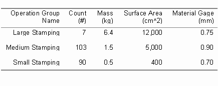
The definition of an operation group for assembly works in much the same manner as for fabrication. The starting point is an estimate of the total number of “joins.” In the case of the steel unibody, these joins are assumed to be spot welds. The second step is the selection of different types of welding operations. These are manual and automated subassembly and manual and automated final assembly. The last step before defining the process characteristics (weld speed, labor count, equipment and fixture cost, etc.) for each “average” operation is to define the percent of total welds performed by that operation. The number of stations of each operation type is then calculated based on the required weld count coupled with the speed and number of each piece of weld equipment within the average station. The table below shows part of a sample assembly operation group definition. 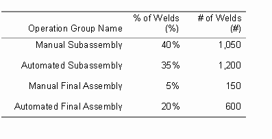
Once operation groups are defined, the next step is to calculate the cost for each average operation by conventionally applying cost analysis (i.e., by assuming that the average operation represents a specific operation with a known material content, production rate, labor requirement, equipment and tool cost, and so on). The cost for all operations of a given type is then found by multiplying the cost of the average operation by the number of operations of that type. Using the “Large Stamping” operation from the fabrication example above, if the cost per stamping is $25, then the cost of all 7 large stampings is $175. Similar multiplications are performed for each fabrication and assembly operation group. Finally, the results are summed to yield an overall cost. To validate the operation group approach, a part list for a recently manufactured body-in-white is used as a basis. This part list contains the part name and material, part mass, and part thickness for approximately 175 pieces (which excludes small brackets). A cost analysis was performed using the full part list and internally developed assumptions for the manufacturing scenario. A second independent analysis used the part list to create 12 part groups representing the same 175 pieces. This operation group design is then used to perform a second analysis. The difference between the two costs is less than 1% of the overall costs that were on the order of $1,000. The list of inputs necessary to cost out the design is long; predictive relationships for equipment and tooling costs are used to shorten this list. In many instances, specific process parameters such as production rate, machine size, machine cost, and tool cost are not known for a specific design. Determining these parameters conventionally involves considerable time by manufacturing experts. This time and expertise may not always be available. The problem is compounded when piece counts are high as for a conventional BIW. For this reason, a regression analysis-based approach has been developed that relates process parameters to part design. An examples for stamping equipment is outlined below after a brief overview of regression analysis; details of a similar tooling cost analysis are available elsewhere [8]. Regression analysis determines the correlation between input and output sets of data. For the present case, regression analysis relates equipment or tool cost (the output) to attributes (inputs) that describe the part to be stamped: length, width, surface area, number of stamping hits, and the like. Such an analysis uses a dataset with known outputs to derive an equation in which other inputs can be entered for which the output is not known. The graph below shows a relationship for stamping press cost as a function of bolster area and tonnage. The bolster is the press “bed” on which the tool is mounted, and is therefore a function of the size of the blank being stamped. Tonnage is a function (that can also be regressed) of the material strength, the area being formed, and the perimeter being cut or trimmed. The line represents the equation for stamping press cost based on an examination of 68 actual production presses. The individual points represent the actual costs of these presses. As seen by the graph and the R^2 value (0.94), the fit is exceptional. 
|
|
CASE STUDY DEFINITION
The basics of the design for the steel unibody, discussed in more detail below and in the Steel Unibody Overview section, are as follows.
The steel unibody part definition is broken down for the three major press types: press line (tandem), transfer, and progressive die. Inputs shown include part count, average mass, average surface area, average gauge, and hits per part. The hits per part column shows how many forming and trimming hits are required to convert the incoming blank to the final part. 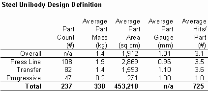
For the fabrication of this steel unibody, key inputs include the following. For the fabrication parameters, “runs” are used instead of parts, where a run might be either one or two parts depending upon whether the stamping is performed single- or double-attached. Key inputs include press speed (“clean,” without downtime, which is factored in elsewhere in the analysis), labor count, and equipment and tooling cost. 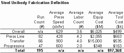
The important assembly inputs are shown in the table below. For each of the four assembly “types,” inputs are shown for the breakdown of welds as well as operating parameters including labor, equipment, tooling (fixtures), and number of stations. 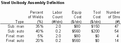
Collectively, these and other inputs are used to generate the cost analysis elaborated on in the following section. |
|
COST ANALYSIS
The figure below presents a cost breakdown for the steel unibody as defined earlier in this paper. The overall cost per body-in-white ready for the paint shop is just over $1,200. Of this cost, roughly 3/4 is in fabrication with the remaining 1/4 coming in assembly. Of the fabrication cost, variable costs in the form of materials and labor account for approximately 1/2 and 1/6 of the cost, respectively. For variable costs on the assembly side, labor is by far the largest contributor at nearly 2/3. 
The allocation of fixed costs account for the bulk of the remaining costs. For fabrication, equipment and tooling make up 1/6 and 1/9, respectively. For assembly, the same contributions are 1/6 and 1/12. Another way to examine these costs is by ranking the major elements in order of overall contribution, which results in the following.
This listing becomes a blueprint for pursuing cost reduction options. Each of these elements is addressed in turn in terms of cost reduction potential. |
|
Fabrication Material
The primary drivers behind material cost are vehicle mass, material price, and engineered scrap. Vehicle mass clearly presents a cost reduction target; programs within the automakers and externally such as ULSAB are working diligently to explore mass reduction avenues. Steel prices, on the other hand, do not likely offer much potential for reduction. While it is possible that technologies such as improved continuous casting might be able to provide lower price steels in automotive grades, large breakthroughs do not appear likely. As with BIW mass, the third fabrication material cost driver, engineered scrap, is also an area worth pursuing. Current scrap rates are on the order of 40% to 50%. A reduction of 15% through more efficient material utilization, say from 45% to 30%, on a 330 kg BIW could result in as much as a $70 savings (6%). |
|
Assembly and Fabrication Labor
Labor costs are driven by the number of laborers, the wage paid to these laborers, and the rate of production. While the number of laborers may be reduced via increased automation, the overall cost effect is not strong. In North America, wages are set by union contracts and are a poor target for cost reduction. Production rates for fabrication and assembly are already quite fast, so this too appears not to be a strong candidate for cost reduction, with the exception of reducing fabrication stamping plant downtimes, which currently may exceed 50%. |
|
Fabrication Equipment
With the exception of facility downtime, which was mentioned for fabrication labor, above, fabrication equipment does not offer much potential for cost reduction. While stamping presses tend to be relatively expensive, they are also quite fast. At medium to high annual production volumes (above 100,000 vehicles per year), this combination already leads to relatively inexpensive manufacturing. |
|
Fabrication Tooling
Stamping tools are relatively expensive, they are dedicated to a particular vehicle or family of vehicles (unlike non-dedicated stamping presses that might be used for other parts), and they have short lives (4-6 years) compared with the 20+ year life of a press. The expensive nature of stamping tools provides the largest opportunity for cost reduction in tooling cost per BIW. A significant portion of the typical $0.5M to $2.5M cost per tool set is the result of changes to the die set design. Through better systems management, it should be possible to reduce this inefficiency significantly. |
|
Assembly Equipment
Assembly equipment does not offer much potential for cost reduction. As was already pointed out, assembly is performed at a high production rate. The individual equipment and robot costs are not particularly high when compared with stamping presses even given the amount of assembly equipment required in a typical body shop. |
|
CONCLUSIONS
This paper lays out and applies a method for simulating the manufacturing cost of a generic steel unibody for which no specific design exists. The ability to perform such an analysis without proprietary information does two things. First, the generic approach allows non-automaker players such as material suppliers to better understand the relative cost position of different material and process technologies. Second, the generic analysis can be used as a common language for automakers to use when talking with one another--for instance, as part of the Partnership for a New Generation of Vehicles (PNGV)--program without having to reveal proprietary information. With respect to avenues for cost reduction in the steel unibody, several major areas for exploration are listed below in order from most to least significant.
Collectively, these areas are the Achilles’ Heel of steel unibody manufacturing cost. As such, they are doors for the steel industry to close or through which the aluminum and composites industries might enter. Without getting into the issues of performance differences offered by the alternative material systems, whoever gets to these doors first will have a decided advantage in the future of automotive material supply. |
|
REFERENCES
[1] John V. Busch, Technical Cost Modeling of Plastics Fabrication Processes, Ph.D. Thesis, Massachusetts Institute of Technology, Cambridge MA, 1987. back [2] Jeff R. Dieffenbach, "Technical Cost Modeling: A Cost Simulation Tool for Material and Process Selection," International Forum on Design for Manufacture and Assembly, Boothroyd and Dewhurst, Inc., Wakefield RI, 1992. back [3] Jeff R. Dieffenbach and J. Bruce Emmons (Autokinetics), "A Manufacturing Cost Analysis of Tube and Node Steel Spaceframes," 1994 Society of Automotive Engineers International Congress, Warrendale PA, February 1994. back [4] Jeff R. Dieffenbach, Paul D. Palmer, and Anthony E. Mascarin, "Making the PNGV Supercar a Reality With Carbon Fiber: Pragmatic Goal or Pipe Dream?," 1996 Society of Automotive Engineers International Congress, Warrendale PA, February 1996. back [5] John V. Busch and Jeff R. Dieffenbach, "Economic Criteria for Sensible Selection of Body Panel Materials," 1991 Society of Automotive Engineers International Congress, Warrendale PA, February 1991. back [6] Jeff R. Dieffenbach and Andrew Sokol (Sokol Enterprises), "Solventborne Painting of a Steel Autobody: A Manufacturing Cost Analysis of Conventional and UV Bake Curing," 1995 Society of Automotive Engineers International Congress, Warrendale PA, February 1995. back [7] Jeff R. Dieffenbach, Anthony E. Mascarin, and Michael M. Fisher (SPI), "The Automobile Recycling Infrastructure: Process Cost Simulation," 1993 Society of Automotive Engineers International Congress, Warrendale PA, February 1993. back [8] Jeff R. Dieffenbach and Jay F. Wzorek, “Predicting Tooling Costs Using Regression Analysis,” Technology Management Report, 1996 11.4:158-161. back |